
 EN
EN
 ar
ar bg
bg hr
hr cs
cs da
da nl
nl fi
fi fr
fr de
de el
el hi
hi it
it ko
ko no
no pl
pl pt
pt ro
ro ru
ru es
es sv
sv tl
tl iw
iw id
id lv
lv lt
lt sr
sr sk
sk sl
sl uk
uk vi
vi et
et hu
hu th
th tr
tr fa
fa ms
ms hy
hy ka
ka ur
ur bn
bn mn
mn ta
ta kk
kk uz
uz ku
ku
Real-Time Dam Safety Alerts with Differential Pressure Water Level Sensors
Key Takeaways An alert chain needs more than a sensor: define field in...

4 Wire Load Cell Connection: Wiring Diagram & Practical Tips
When you first unbox a 4-wire load cell, the four colored leads can feel like a small puzzle. A good wiring diagram clears that up fast, but knowing why the wires go where they do saves you from chasing noise or drift later. This guide walks through a typical connection for a 4-wire strain gauge load cell, covering the signal and excitation pairs, shielding practices, and a few field-tested tips. Kingmach, a mid-range geotechnical instrument manufacturer, ships many of its load cells with standard color coding, but we’ll stick to the generic labels—Excitation+, Excitation–, Signal+, Signal–—so you can adapt it to any brand. Whether you’re wiring into a PLC, a weight transmitter, or a simple amplifier board, the fundamentals stay the same. We’ll also flag the most common wiring mistakes that lead to unstable readings, so you don’t have to learn them firsthand.
Technical Detail
A 4-wire load cell has two pairs: one carries the excitation voltage to the Wheatstone bridge, the other brings back the tiny millivolt signal. The diagram looks simple enough—Exc+ and Exc– to a stable power supply, Sig+ and Sig– to your amplifier or ADC. What doesn’t show on paper is that every inch of wire between the cell and the electronics can act as an antenna. That’s where shielding comes in. The cable usually comes with a bare drain wire or an overall foil shield. Tie that to a clean ground at one end only—typically at the instrumentation side—to prevent ground loops. Kingmach instruments fall into a mid-range price tier, built for reliability in structural monitoring and geotechnical applications. Their load cells typically follow the common color codes you’d expect, but since codes vary between manufacturers, always check the datasheet that ships with the cell. If the sheet is lost, a quick resistance check with a multimeter will identify the pairs: the excitation pair usually has a lower resistance (around 350Ω or 1kΩ), and the signal pair reads slightly higher. One practical note: avoid routing load cell cables parallel to high-current AC lines. If you must cross such lines, do it at a right angle. Junction boxes with screw terminals are common for summing multiple cells; keep the individual leads short and the cable to the junction box as symmetric as possible. Kingmach provides technical support for these setups, which can be helpful when you’re dealing with a 6-wire upgrade or a mixed-vendor system. For permanent installations, many engineers add a local junction box with a precision resistor network to trim corner errors. That’s beyond a basic 4-wire connection, but it’s worth knowing that a clean initial wiring pays off when you start calibration. Kingmach’s technical team often recommends a quick sense-lead check—measuring the excitation voltage right at the cell connector—to catch voltage drop before it ruins your data. Small steps like this turn a wiring diagram into a reliable measurement chain.
News
Key Takeaways An alert chain needs more than a sensor: define field in...

Key Takeaways The strongest fit is usually a confined, submerged, or s...

Kingmach Water Level Sensors for Dam Monitoring: A Buyer's Guide to Differential Pre...
Products
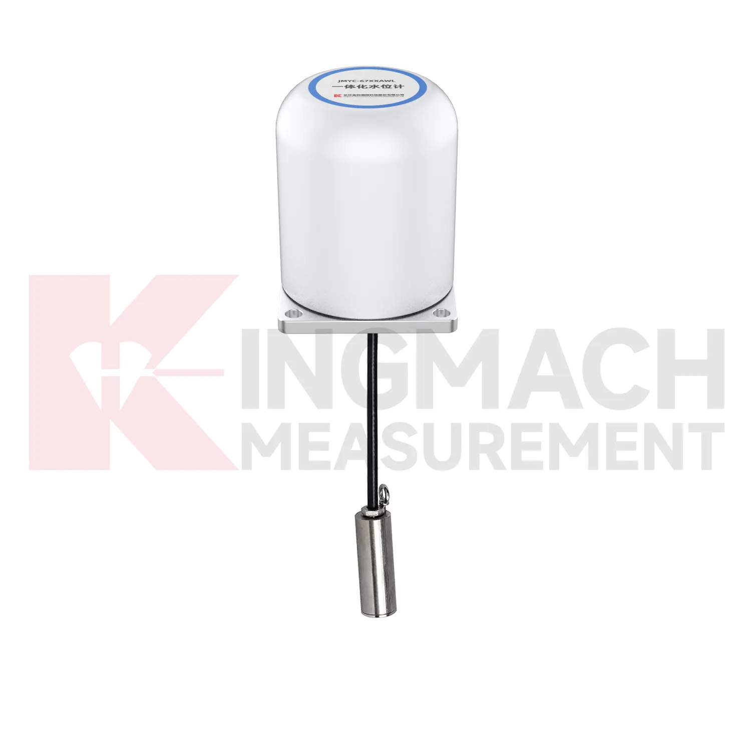
Integrated Wide-Range Differential Pressure Water Level Meter JMYC-67XXAWL
View Details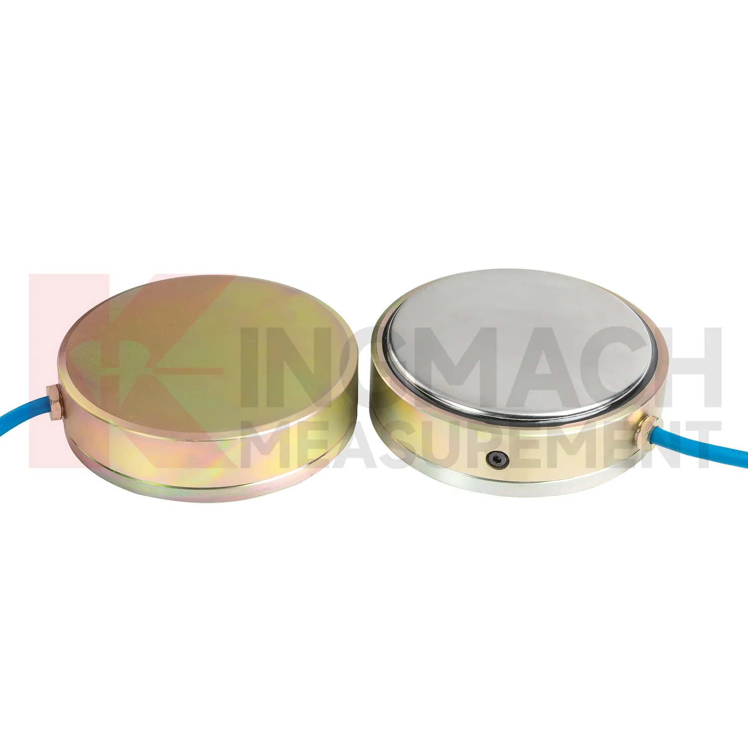
Large Earth Pressure Cell ( VW & Smart Type) JMZX-51XXAT/ ATM
View DetailsFAQ
There’s no universal standard, so always check the manufacturer’s datasheet. A common arrangement is red for Exc+, black for Exc–, green for Sig+, and white for Sig–, but it can be different. If you don’t have the sheet, measure resistance between leads. The pair with lower resistance (often 350Ω or 1kΩ) is the excitation pair; the other is the signal pair. Connect the excitation leads to your power supply first, then verify the signal polarity with a small test weight.
Drift can come from several sources. First, check that the shield wire is connected at one end only (usually the amplifier). If both ends are grounded, a ground loop can inject noise. Second, make sure you’re using the correct excitation voltage—overexciting can heat the strain gauges and cause drift. Third, look for moisture in the connector or junction box; even slight corrosion can create leakage paths. If the cell is new and these steps don’t help, contact Kingmach’s support for troubleshooting.
Yes, but you’ll introduce voltage drop in the excitation leads, which slightly reduces the sensitivity. For short extensions (a few meters), the error is usually negligible if you’re within the amplifier’s tolerance. For longer runs, consider switching to a 6-wire configuration where two sense leads compensate for the drop. When extending, keep the splice shielded and watertight. Kingmach can supply pre‑wired extension cables that match their load cell color codes to reduce mistakes.
Most likely the signal polarity is reversed. Swap the two signal wires (Sig+ and Sig–) at your amplifier input. If the reading becomes positive, you’ve flipped polarity. A small zero offset is normal; many instruments have a zero/tare function to eliminate it. If the offset is very large, check for a damaged load cell cable or terminal block by measuring the signal voltage at zero load—it should be close to zero millivolts relative to the excitation.
You’ll need a summing junction box. Inside it, each load cell’s excitation leads connect in parallel to the power supply (maintaining Exc+ and Exc–), and each signal pair connects through a summing network to provide one averaged Sig+ and Sig– to the amplifier. Make sure all load cells have the same rated output and capacity, and keep the wiring symmetrical to avoid angle errors. Kingmach offers junction boxes with built‑in trimmers for corner balancing.
Share your product type, target capacity, and application requirements. Our team can review the details and recommend a practical next step.
If you are interested in our products or want to become our partner.
Please leave your contact information, our team will contact you as soon as possible.
Mail: [email protected]
Contact Us: +8613808434127
Address: No. 188 Tongzipo West Rd, Changsha, Hunan, China