 ar
ar bg
bg hr
hr cs
cs da
da nl
nl fi
fi fr
fr de
de el
el hi
hi it
it ko
ko no
no pl
pl pt
pt ro
ro ru
ru es
es sv
sv tl
tl iw
iw id
id lv
lv lt
lt sr
sr sk
sk sl
sl uk
uk vi
vi et
et hu
hu th
th tr
tr fa
fa ms
ms hy
hy ka
ka ur
ur bn
bn mn
mn ta
ta kk
kk uz
uz ku
ku
load cell wiring diagram
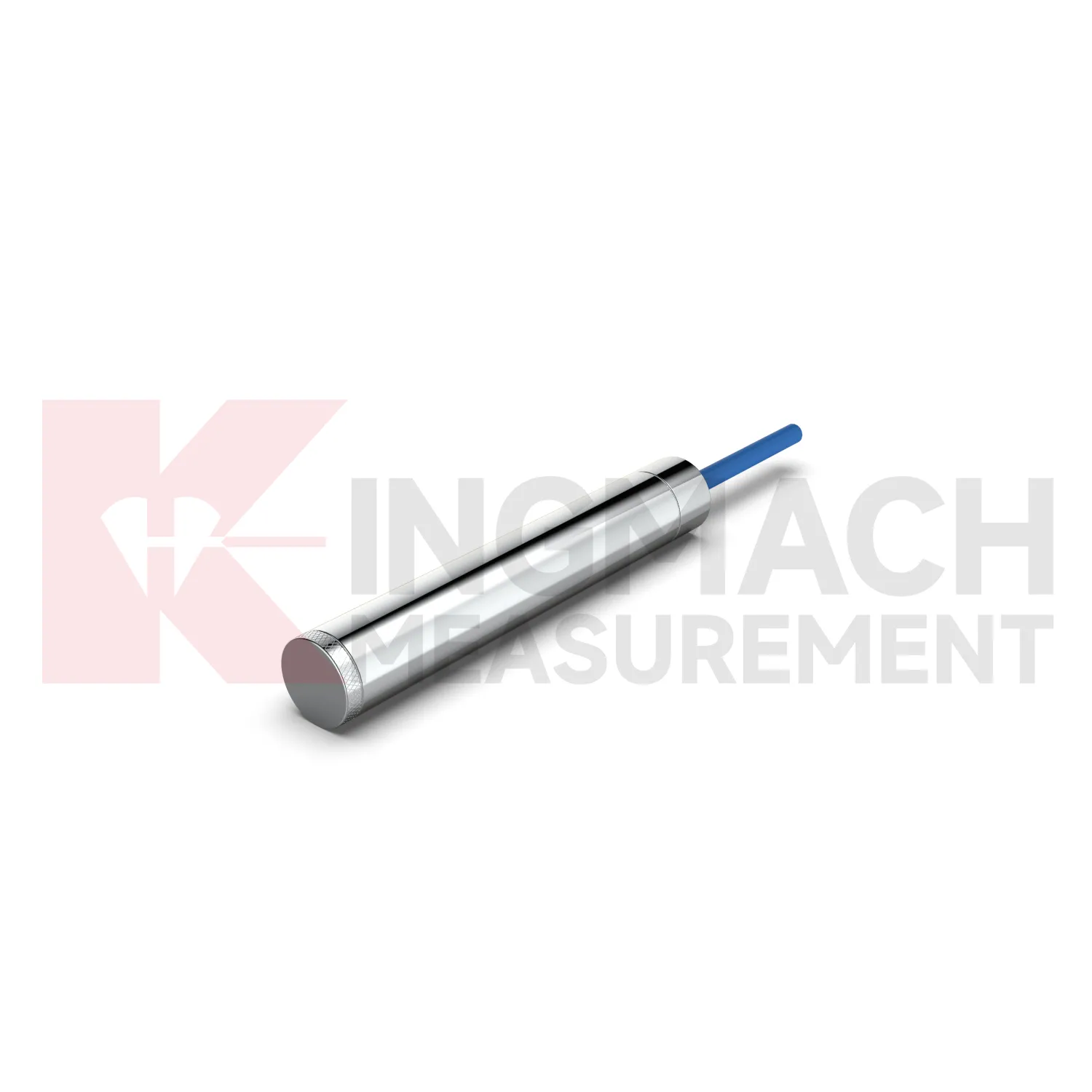
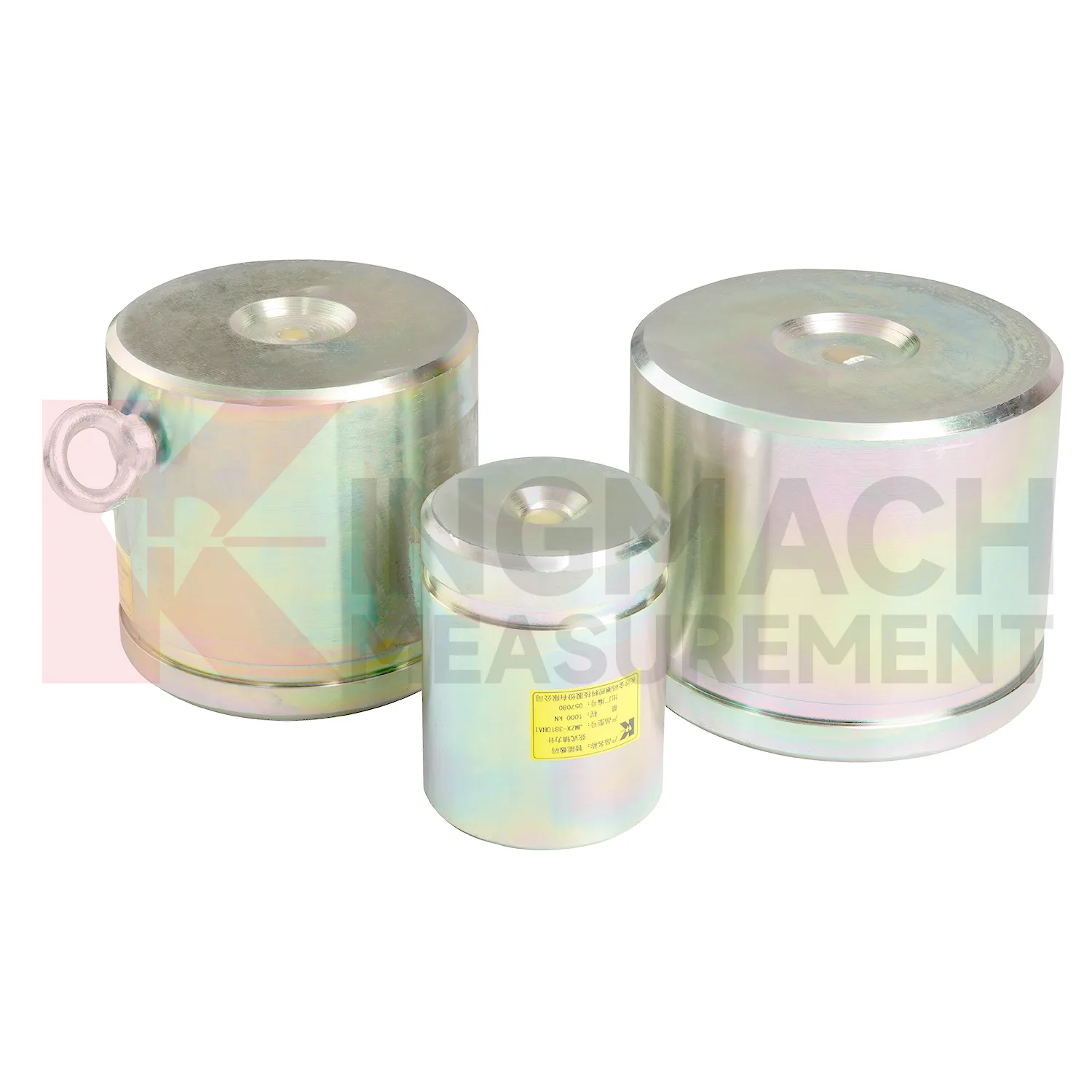
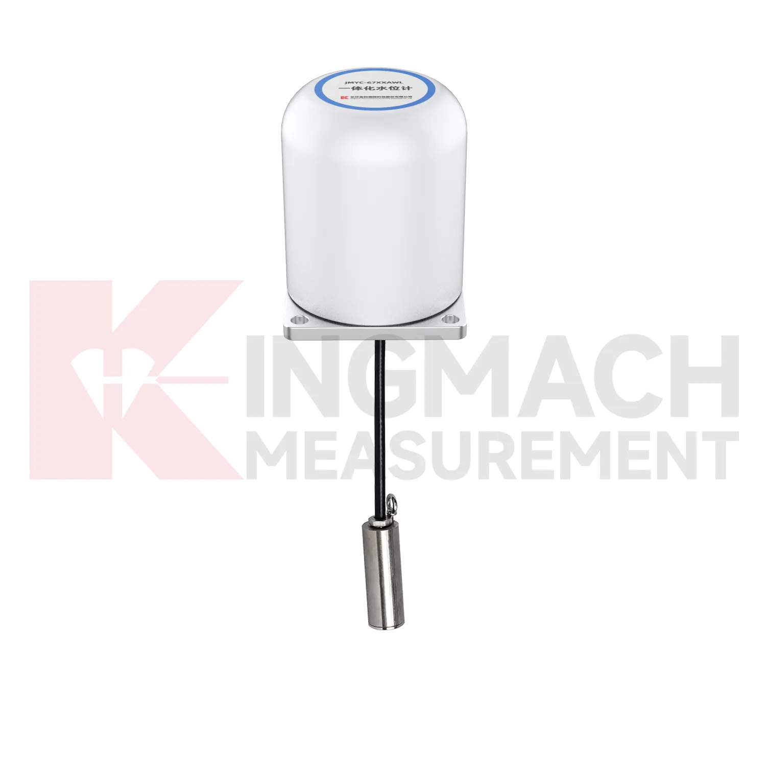
Kingmach load cell wiring diagram covers more than one mechanical form, which matters because force does not enter every structure the same way. The solid load cell JMZX-35XXHAT is listed for 1000 kN to 10000 kN with 0.1 kN resolution and 0.5%FS precision. The same product file gives a -30°C to 80°C working temperature range, 20 to 50%F.S. range overload, and 300 to 400%F.S. failure overload. It also stores model, number, calibration coefficient, pressure value, zero parameter, and temperature correction data. These points make it better suited to compression load checks such as pile load testing, bridge pier support measurement, and heavy structural bearing work. The instrument is part of a larger Kingmach monitoring catalog that includes displacement, settlement, tilt, pressure, water level, and acquisition products. For procurement, the practical review should cover capacity margin, bearing surface geometry, calibration documents, expected temperature range, overload exposure, and whether the readings will be taken locally or fed into an automated system. Kingmach also presents the product family alongside project areas such as bridges, dams, tunnels, subways, slopes, buildings, subgrades, wind towers, and foundation pits. That makes the specification less abstract: each model can be matched to a known load path and a known field environment before ordering.
Application of load cell wiring diagram
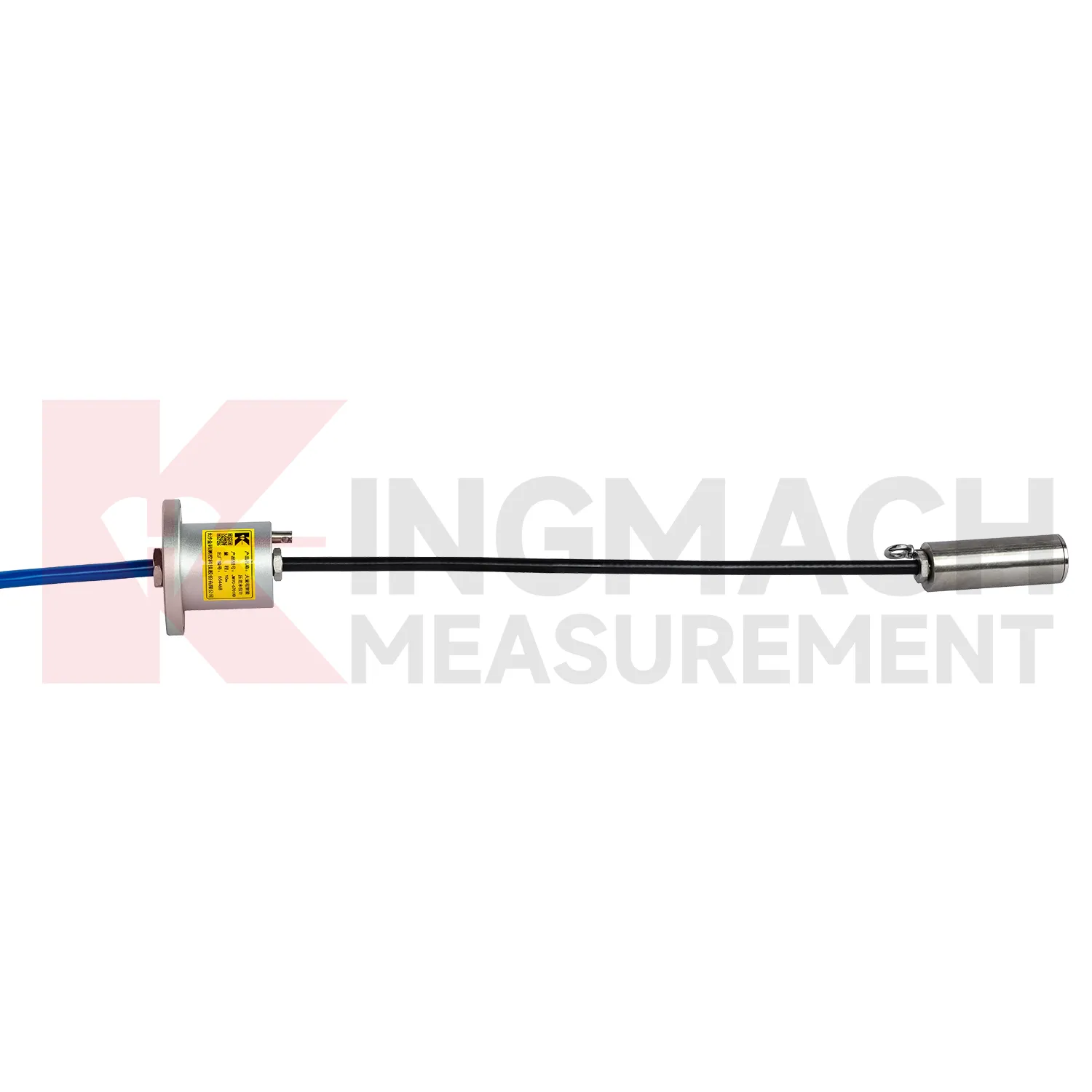
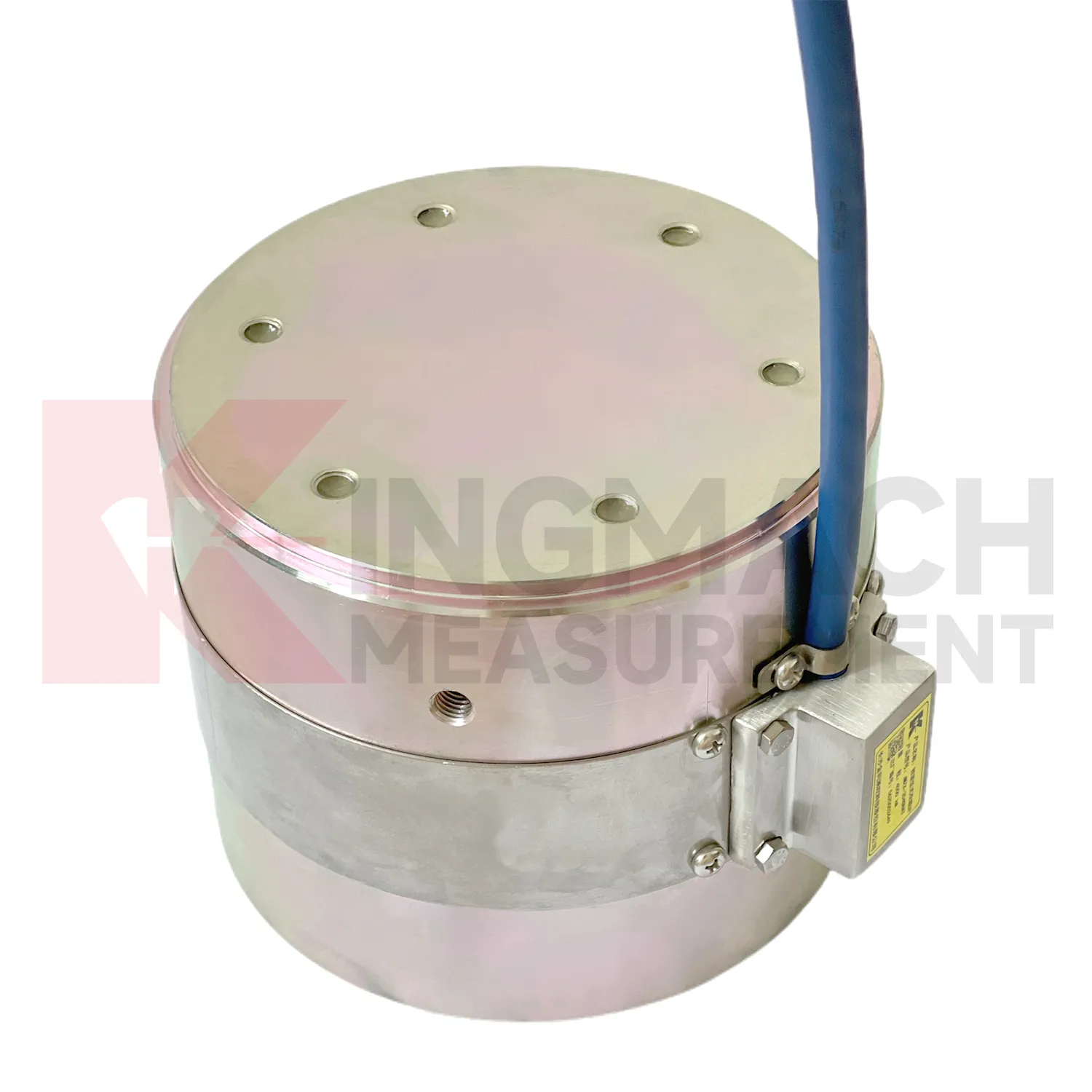
In building structural health monitoring, load cell wiring diagram can be used around transfer structures, temporary supports, column load checks, foundation testing, and heavy equipment installation areas. The monitoring need is often construction stage control rather than a permanent visible defect. Loads may shift when floors are cast, jacks are released, shoring is removed, or new equipment is placed. Kingmach solid load cells offer 1000 kN to 10000 kN ranges, 0.1 kN resolution, and 0.5%FS precision, with a -30°C to 80°C working temperature range. Axial force meters add direct kN display for steel support points and 0.5%FS accuracy. These parameters help site teams check whether the support path is behaving as planned. The reading should be reviewed together with settlement, tilt, crack gauges, and construction sequence notes. For long term building owners, retaining the original model, calibration coefficient, zero value, and first stable reading makes later inspection far easier when occupancy, equipment load, or renovation changes the load pattern. In buildings, temporary works often disappear after the next construction stage, so the early record should be complete. Photographs of the installed point, bearing plates, cable path, and readout channel can prevent confusion during later structural review.
The future of load cell wiring diagram
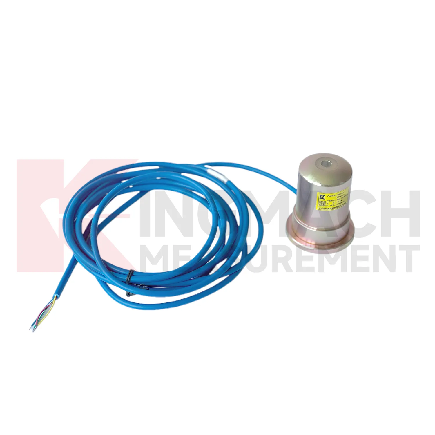
Future load cell wiring diagram use will depend on cleaner data pipelines, not only stronger metal parts. Kingmach's smart load cell features, including digital output, long distance transmission, anti-interference performance, temperature correction, and stored parameters, already point toward connected monitoring. In the next few years, more projects are likely to use edge acquisition units that check whether a reading is plausible before it reaches the platform. A sudden force jump can be compared with temperature, cable condition, nearby displacement, and recent construction events. AI based warning tools may help sort routine fluctuation from patterns that deserve inspection, but they will only work when the instrument record is consistent. That places more value on channel naming, calibration certificates, zero checks, installation photos, and maintenance logs. The product direction is therefore practical: robust sensing at the point of load, reliable transmission from difficult sites, and software that helps engineers review trends without losing the original measurement context.
Care & Maintenance of load cell wiring diagram
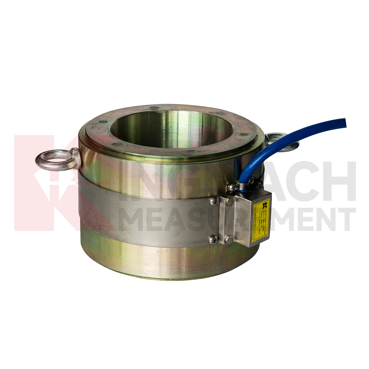
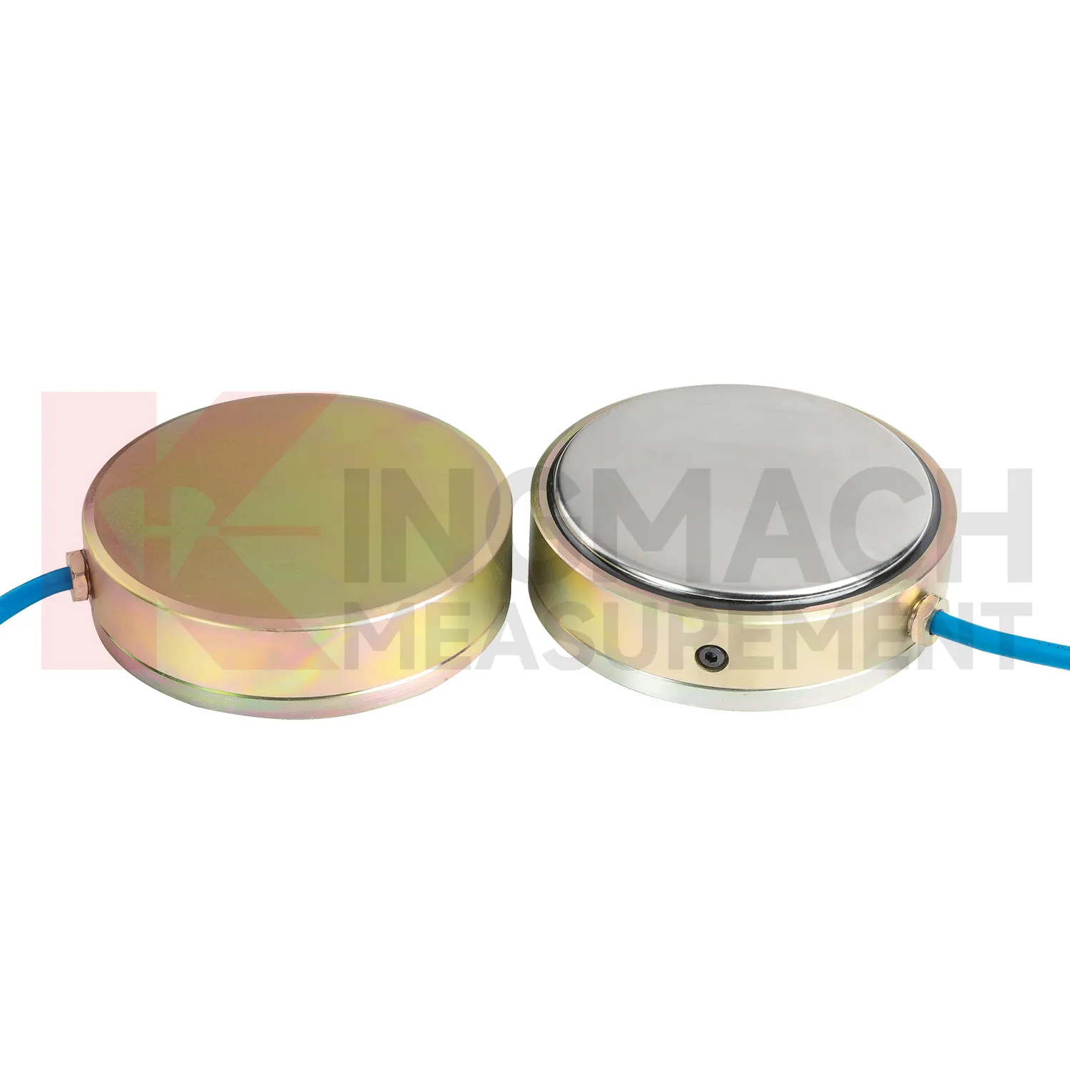
For load cell wiring diagram, installation quality usually determines whether later maintenance is simple or painful. Before loading, confirm the model, range, calibration coefficient, zero value, bearing surface, and cable route. Hollow load cells may cover 500 kN to 8000 kN, while solid load cells may reach 10000 kN, so capacity should be checked against both working load and possible overload. During installation, keep bearing plates flat and strong enough to avoid stress concentration, especially on axial force meters and compression load points. Protect cables from bending, pulling, welding sparks, crushing, and water entry at connectors. After the first stable reading, record temperature, channel name, instrument serial information, and site condition. During long term use, inspect sealing, cable jackets, junction boxes, and acquisition channels after rainfall, excavation changes, jacking, or impact. If a value drifts, check temperature, connector condition, zero history, and nearby sensors before assuming the instrument has failed. Document who made the check.
Kingmach load cell wiring diagram
load cell wiring diagram often sits between design intent and field behavior. Drawings may state the expected force, but site loading can change when excavation sequence, concrete curing, traffic, reservoir level, grouting, or prestressing work changes. Kingmach supplies sensors and acquisition equipment for bridges, tunnels, dams, subways, slopes, foundations, railways, buildings, and hydropower projects. In these settings, the sensor helps reveal whether a member is carrying its share of the load or taking more than expected. The instrument must fit the force range, the bearing surface, the environmental exposure, and the data workflow. A high capacity sensor with poor installation records is still hard to trust. A moderate range sensor with clear calibration, stable zero, protected cable, and a clean reading plan can produce stronger evidence. For that reason, force monitoring should be planned alongside installation details, not added after the site has already become crowded. This is especially useful when the monitored point becomes hidden after the next work stage.
FAQ
Q: Can load cell wiring diagram be used for soil pressure or retaining wall pressure? A: Yes, pressure related models such as earth pressure cells are used where the measured value is contact pressure rather than direct member force. Q: What ranges are listed for Kingmach earth pressure cells? A: The JMZX-50XXAT/ATM family lists 0.3 MPa, 0.6 MPa, 1 MPa, 2 MPa, 4 MPa, 6 MPa, and 8 MPa ranges. Q: What accuracy and resolution are listed? A: The product file gives 0.001 MPa pressure resolution, 0.5%FS pressure accuracy, and ±0.5°C temperature accuracy. Q: Where are these readings useful? A: Foundation pits, dams, slopes, retaining walls, embankments, tunnels, and buried structures. Q: What maintenance issue is most common? A: Cable damage, water entry, channel confusion, and poor installation records cause many field doubts.
Reviews
Michael Anderson
The strain gauges and load cells are extremely accurate and stable. They performed very well in our bridge monitoring project. Highly recommended!
Matthew Garcia
Instrumentation cables are durable and perform well even in harsh environments. Will definitely order again.
Latest Inquiries
To protect the privacy of our buyers, only public service email domains like Gmail, Yahoo, and MSN will be displayed. Additionally, only a limited portion of the inquiry content will be shown.
Emma***@gmail.comCanada
Dear Sir/Madam, we are interested in displacement transducers and settlement sensors for a geotechni...
Ava***@gmail.comAustralia
Hi, I am looking for reliable tiltmeters and accelerometers for structural health monitoring. Please...